Dynamic Field Camera™
You would not debug an electrical circuit without an oscilloscope, why would you do MR methods development without a field camera?
- The gradients of every MR system have non-idealities that result in imperfect image encoding
- Debugging and optimizing advanced pulse sequences is labor intensive and error prone without direct measurement tools
- Characterization of gradient systems under operant conditions fully captures dynamic interactions
MR Methods developers aim to deliver novel imaging technologies that acquire images with greater speed and SNR or that contain a new type of data useful to biomedical and clinical researchers.
Programming and validating new gradient waveforms for pulse sequence development can be cumbersome without the right tools. Vendor-provided pulse sequence programming environments often include simulation tools; however, these tools often reflect an idealized model of the scanner’s physical environment and therefore may not provide a comprehensive analysis of the sequence’s performance. Direct measurement of a pulse sequence, particularly gradient pulses, removes much of the uncertainty from pulse sequence programming and validation and is the key to generating novel, geometrically accurate images.
Similarly, while electromagnetic modeling provides a great deal of insight into the performance of new gradient systems, direct measurements in situ ensures that the gradient performance meets the design specifications. In situ measurements also provides you unprecedented insight into all of the interactions between the gradient and other scanner systems.
Oscilloscope for MRI
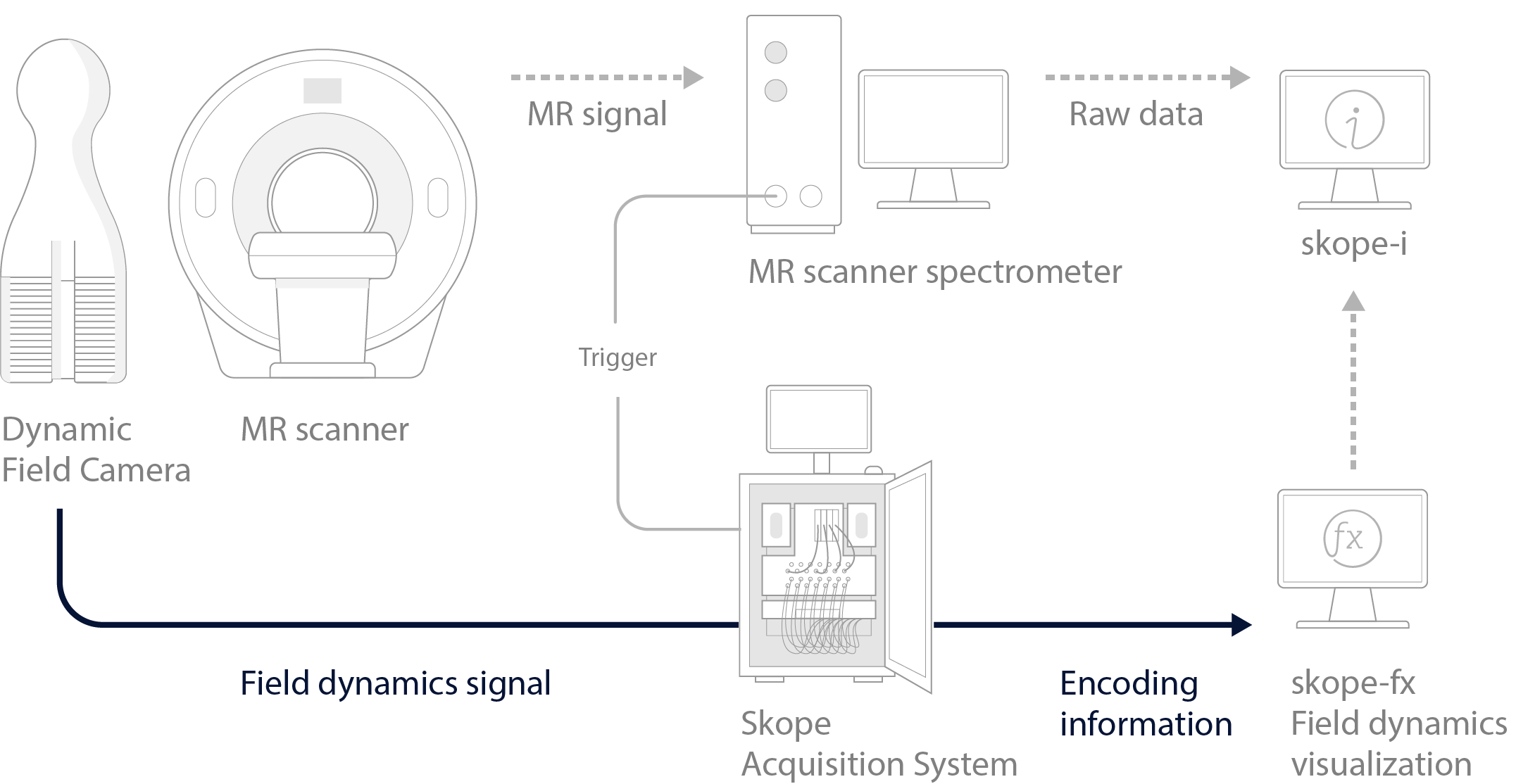
The Dynamic Field Camera provides researchers with direct measurements of the dynamic magnetic field of the scanner, allowing for characterization of the gradients, dynamic changes in B0, and transient fields including eddy currents and gradient cross term interactions. Field measurements are made using an optimized arrangement of our advanced and patented NMR field probe sensors.
The Dynamic Field Camera gives pulse sequence designers direct insight into the evolution of the magnetic field of their scanner and sequence. It provides measurements of gradient fields, k-space trajectories, and higher-order spherical harmonic representations of the field. This does not rely on any other component of the MR system to measure the scanner’s encoding fields, but is a fully independent measurement.
Gradient performance in real world conditions exhibit a number of non-idealities that are not frequently considered in pulse sequence development but have a direct impact on image quality. Gradient cross terms and eddy currents are examples of these, with eddy currents from diffusion encoding gradients affecting the spatiotemporal phase evolution during the imaging readout module, which for an echo-planar readout causes image stretching and skewing characteristic to each diffusion direction. Measuring and accounting for these in reconstruction leads to images with higher SNR and improved geometric accuracy.
Speed up sequence development
The development of novel MR sequences is commonly impeded by unexpected gradient behavior or programming errors, which are cumbersome to investigate. Direct measurement of gradients and k-space trajectories allows researchers to rapidly investigate gradient timings and visualize actual gradient waveforms, in addition to identifying unexpected behavior caused by interactions between system components.
Without direct measurement, detecting and rectifying unexpected gradient behavior becomes cumbersome and often requires a combination of intuition and additional pulse sequences to isolate issues. Debugging in this manner is time consuming and frustrating. Visualization of gradient dynamics expedites the debugging process without the need for implementing additional pulse sequences, dramatically reducing the time to successfully implement new MR methods.
 |
Courtesy: Denizhan Kurban, Maastricht University
Enable novel image reconstruction
Courtesy: Nagy Z and Lee YJ, IBT ETH Zurich and University of Zurich
As we increase the capability of MR systems, many of the assumptions we previously made about the encoding behavior of the system may no longer be valid.
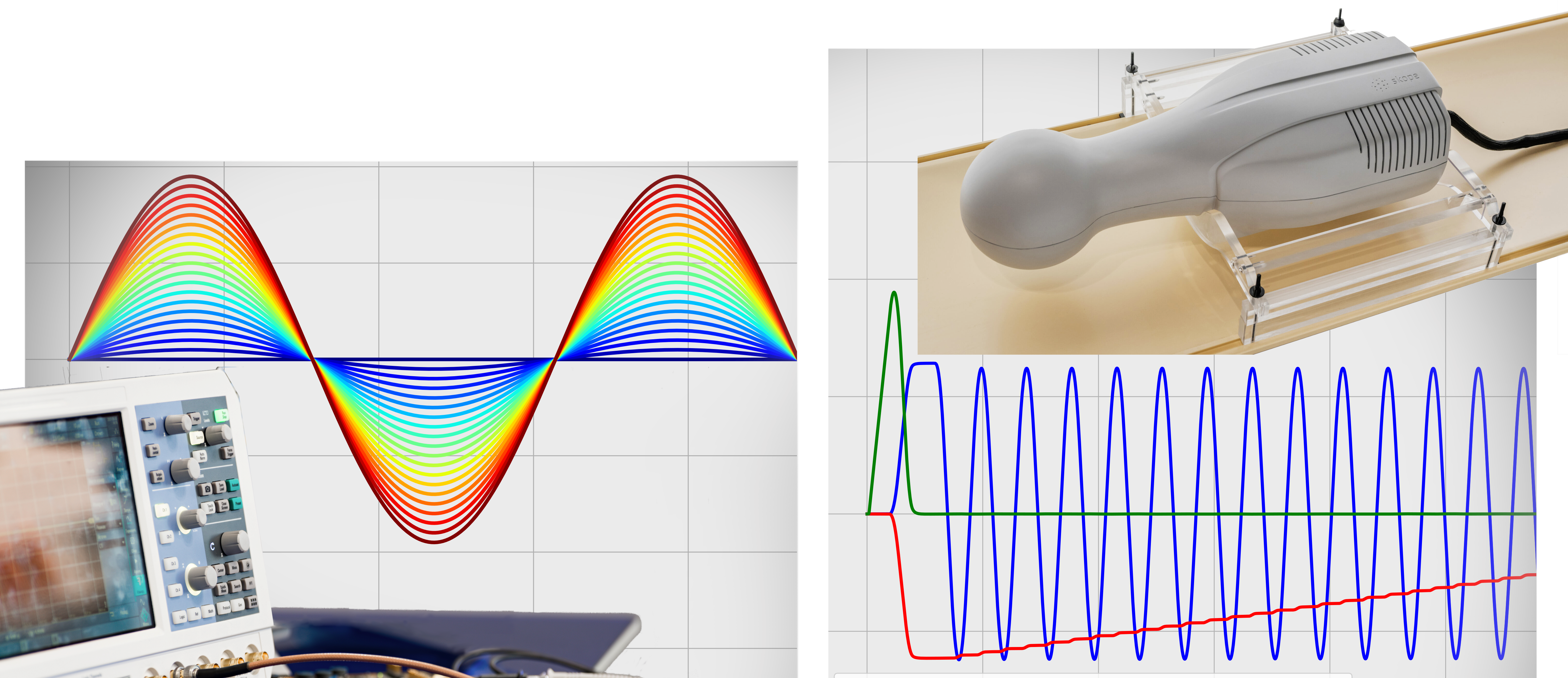
In one example, the ETH Zurich group in collaboration with Philips Research Hamburg constructed an insert gradient system capable of 200 mT/m at 600 T/m/s or 100 mT/m and 1200T/m/s. This system however has more spatial complex time varying magnetic fields. See in the link below how Dr. Hennel utilized multiple Dynamic Field Camera measurements to spatially and temporally resolve the field fluctuations, enabling high quality imaging. Applying this system now to diffusion imaging, we can see how important it is to take into consideration many aspects of the spatiotemporally varying fields.
Characterize and leverage gradient and shim systems
The Dynamic Field Camera allows for accurate characterization of gradient and shim systems (Vannesjo et al. (2013), IBT ETH Zurich and University of Zurich). Acquired measurements can be used to build a linear, time-invariant representation of the gradient chain, called a gradient impulse response function.
The GIRF can be convolved with an arbitrary gradient waveform to estimate the actual gradient waveforms played out by the scanner. The encoding that the MR sample has undergone can also be estimated, allowing you to see how your gradient design impacts image quality before you scan a phantom or try an in vivo acquisition. You can see more by Vannesjo et al. (2012), IBT ETH Zurich and University of Zurich.
GIRF data can incorporated into image reconstructions to yield higher quality images (Vannesjo et al. (2015), IBT ETH Zurich and University of Zurich) or be used to generate novel pre-emphasis schemes by inverting the impulse response function (Vannesjo et al. (2016), IBT ETH Zurich and University of Zurich).
 |
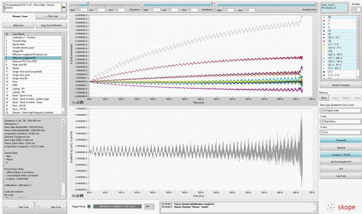
The skope-fx software controls the acquisition and processing of the field data, and allows for a fast and easy visualization.
|
 |
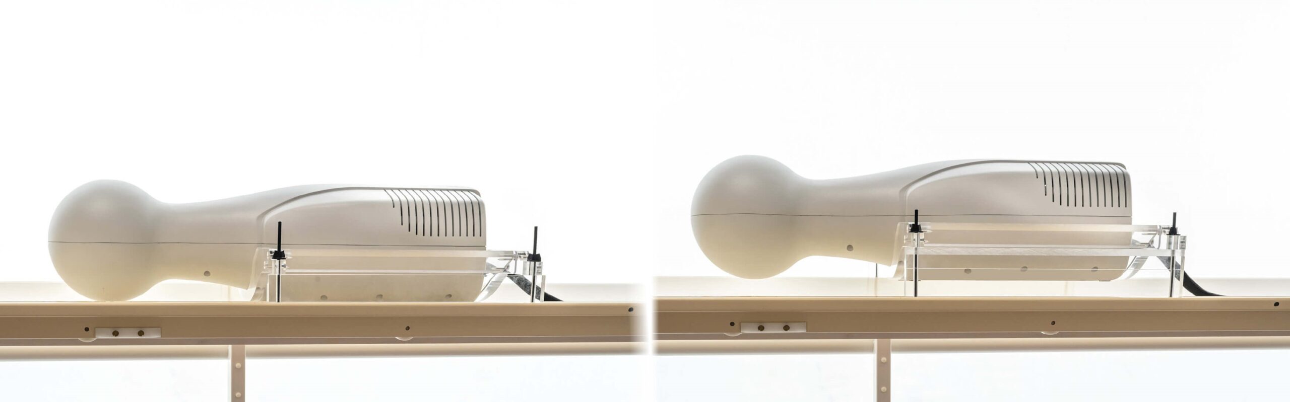
The Table Positioning Unit allows for rigid mounting of the Dynamic Field Camera on the patient table. Moreover, it enables the adjusting of the height and orientation of the Dynamic Field Camera.
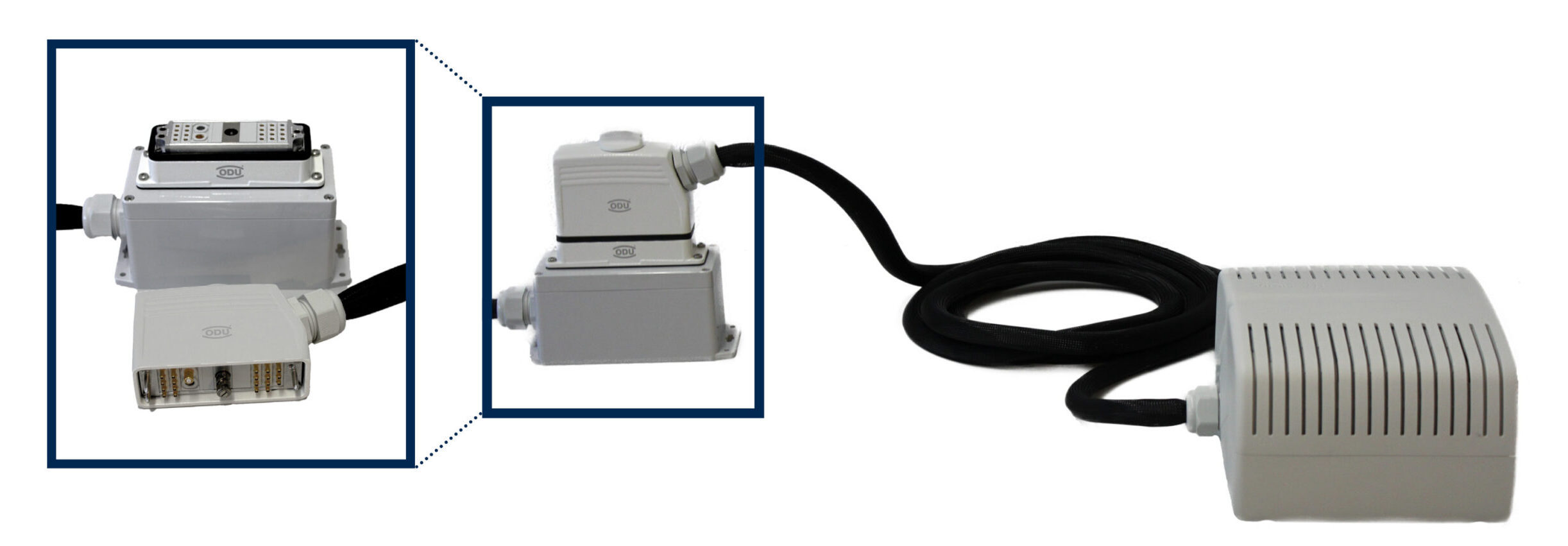
Connect your Skope Camera in one touch and save time when connecting your Skope Camera to the Camera Acquisition System.